Lock and shimming are very important for getting a good line shape. If the lock level is smaller than 10 after shimming, the lock may fail during the acquisition and lineshape may be bad.
Lock failure and a bad line shape can be found under many different conditions.
(A) user’s problems
1. The sample length is too short.
The minimum sample length is 3.6 cm for 5 mm diameter tube and 2.8 cm for 3 mm diameter tube in the Agilent NMR machines. This will fill the coil with sufficient excess to maintain magnetic field homogeneity. If the sample is too short, the bottom of the tube and the surface between the liquid and air will disturb the homogeneity of the magnetic field around the sample, and will reduce the effectiveness of the gradient shimming, resulting in a bad lineshape. In the worst case, the lock will also fail. Please add enough solvent to meet the length requirement (approximately 600 micro liters in a standard 5 mm diameter NMR tube and 250 micro liters in a standard 3 mm diameter NMR tube).
2. The sample does not sit symmetrically to the center of the coil.
It is important to position the sample symmetric to the center of the coil. In depth gauge, the probe RF coil position is marked by dashed line, while the center is marked (CL) on the long horizontal line, as shown in Fig. 1. If the sample is not centered on the coil, the spectral lineshape will be bad and the lock may fail.
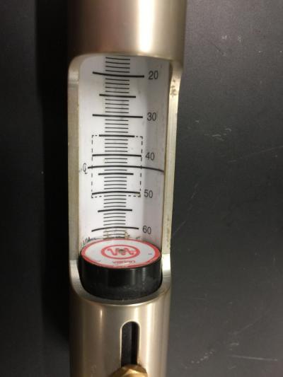
Fig. 1
3. The sample is not all the way in the magnet.
In VT experiments, some users may set the VT gas flow rate too high. As the VT gas flows in from underneath the sample, a rate higher than 18 liters per minute will slightly lift sample, causing its position to deviate from the center of the magnet. Please do not forget to reduce the VT gas flow rate after VT experiments if you have changed it.
(B) Machine’s problems
1. The gradient shimming failed.
A good lineshape needs re-shimming for each sample. The shimming method uses gradients and the gradient amplifier can sometimes fail. If the lineshape is very bad, but you are sure the sample is correctly positioned, look at the back of the console. On the top (Fig. 2) there is a unit “Pulsed Field Gradient Amplifier and Temperature Controller”. On the top of PFG, the “enable” light should be on. On the “Temperature” part, the “STATE” and “ERROR” lights should be off. If either light is on, reset the unit. Turn off the HEATER switch, wait for 10 seconds and turn it back on.
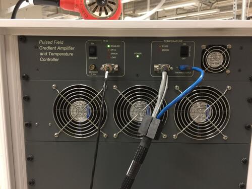
Fig. 2
If the “enable” light on PFG is off after the Heater reset, go to “Start” and hit “Setup hardware” as shown in Fig. 3.
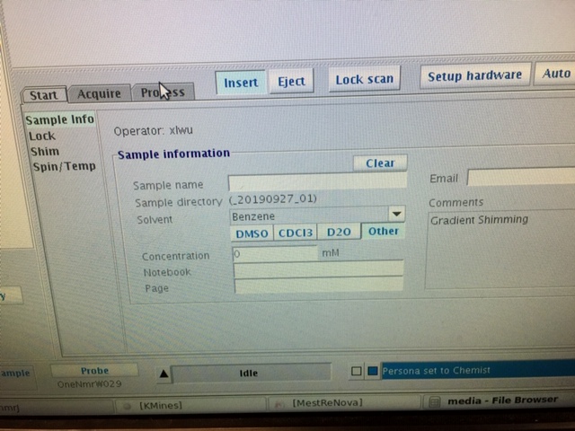
Fig. 3
If the gradient is not back, the the console has to be turned off and wait for a few seconds turn on. The console power switch is on the left side of the bottom of its back as shown in Fig. 4
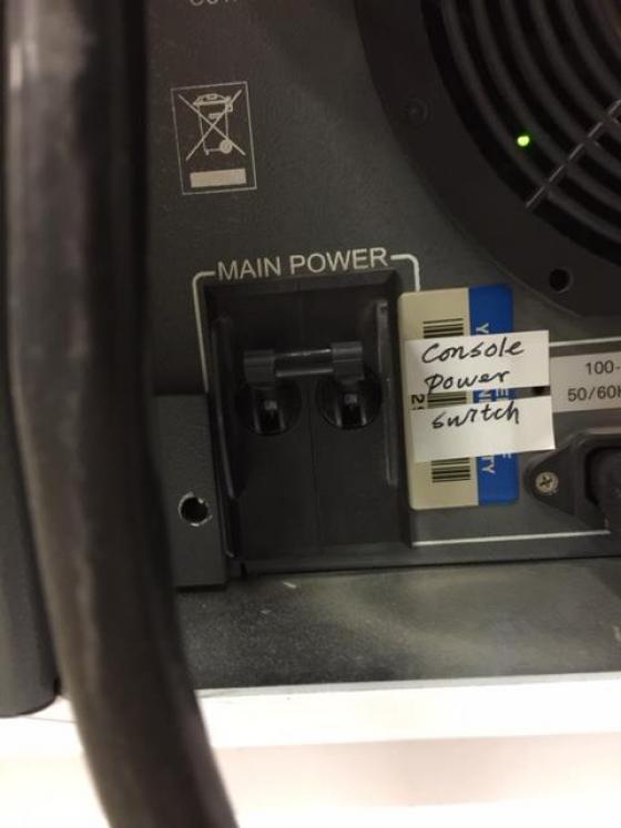
Fig. 4
If needed, you can make a brief test the gradient shimming. On the VnmrJ command line, type ‘gmapsys’, then click “Acquire Trial Spectra”. After the experiment finishes, there should be two square shape lines as in Fig. 5. If the lines are narrow as in Fig 6, the gradient shimming has failed.
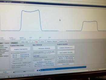
Fig. 5
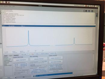
Fig.6
2. The lock phase is wrong.
A correct lock phase is important to keep the lock level high. Wrong lock phase may result in lock lost.
Click “Lock Scan” button, a lock status is displayed as Fig.7.
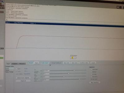
Fig. 7
You may need to increase the lock gain or lock power to see the curves.
If the phase is correct, the blue line should be at zero position of the vertical scale. Otherwise, it will be at negative or positive position as Fig. 8.
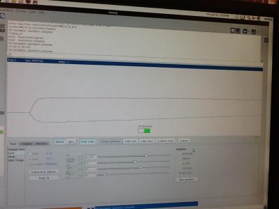
Fig. 8
Change the lock phase value so that the blue line is close to the zero position.
Then exit the “Lock Scan” status by click the button again. Fine change the lock phase value to get a maximum lock level.
The recent correct lock phase value for each machine is:
A400a: 150
A400b: 45
A400c: 155
A500a: 290
A500b: 215
A600a: 25.
The correct lock phase may change due to different reasons. We need pay attention to it.