For more technical details about the recovery manifold located next to each magnet, please see this drawing:
NMR_Helium_Recovery_Manifold.pdf
Update: Instead of the “styrofoam ball” modification we now recommend the following flow meter: Omega FL-7611. This meter should work for most manifolds without modification.
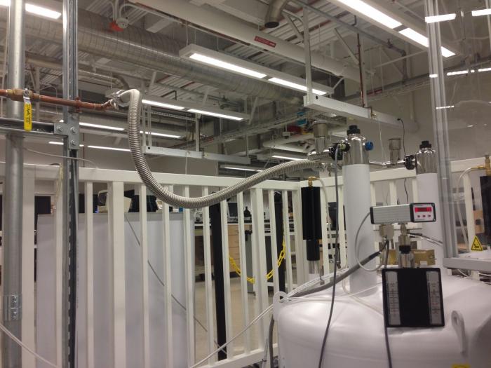
We are using a Cryomech LHeP22 Medium Pressure Helium Recovery system for our NMR magnets. Details about how the magnets are connected to the system can be seen below.
The helium outlet of each magnet is connected to a KF-25 Tee, with one side for high-flow (during fills) and the other for low-flow (during normal boil-off):
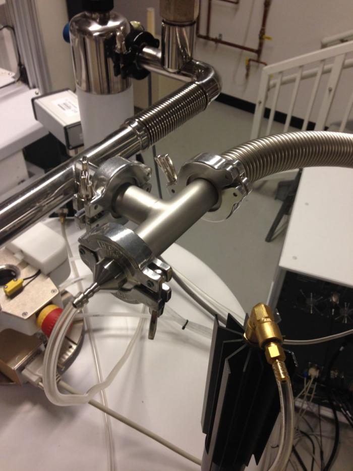
The high-flow side is connected via stainless-steel metal bellows tubing (commonly used for vacuum systems) to provide a leak-free, low back-pressure connection to the recovery system. This connection must withstand the low temperatures of the exhaust gas from a helium fill and also preserve the low-vibration properties of a floating NMR magnet.
The low-flow side is plumbed to via the vendor-supplied connections to the helium boil-off flow meter (seen in the lower right-hand corner of the picture below), allowing us to monitor for leaks or blockage (seen as low- or zero-flow) or problems with the magnet dewar (seen as higher than normal flow):
Note that a ball-valve, located at the wall in the high-flow connection, is normally closed (except during fills) so that the helium is forced down the low-flow side. This ball-valve could be located on the magnet, however this might put excessive weight and stress on the helium stacks of the magnet.
After the helium boil-off flow meter, the low-flow side is then plumbed through an “Adjustable Pressure-Maintaining Aluminum Relief Valve”, also known as a “Back-Pressure Regulator” (currently available from McMaster-Carr). The pressure should be as low as possible, yet set above anything expected “down-stream” in the helium recovery system (i.e. due to fills on another magnet, the recovery bag inflating or deflating, etc.). In our system we are using 0.5 psi, which corresponds to about 35 millibars above atmospheric pressure:

The difference between a normal regulator and a back-pressure regulator is which port (outlet or inlet) controls the flow. On normal pressure regulators (such as used with a cylinder of gas), the outlet pressure controls whether or not the regulator is open to flow. On a back-pressure regulator, the inlet pressure controls this. With a back-pressure regulator, a constant pressure (relative to atmospheric pressure) can be maintained on the magnet, independent of what is happening “down-stream” in the recovery system (as long as the “up-stream” pressure is always higher than the “down-stream” pressure). A simple pressure-relief valve will not work for this purpose – it will add pressure relative to whatever is “down-stream” in the system, allowing for pressure fluctuation. For higher-field systems with a vendor-supplied manostat, we use the manostat instead of the back-pressure regulator. Manostats accurately control the inlet pressure relative to vacuum, rather than relative to atmospheric pressure, and are a better choice if they are available.
Each magnet has its own manifold made of soft-soldered copper pipe, connected to a common header that goes to the helium recovery system. We based our helium manifold on the ones used at Iowa State University (thank you to those who collected and posted information about this!). In the picture below, the high-flow line comes in at the upper right, the low-flow line comes in at the bottom left, and the helium exits at the upper left:
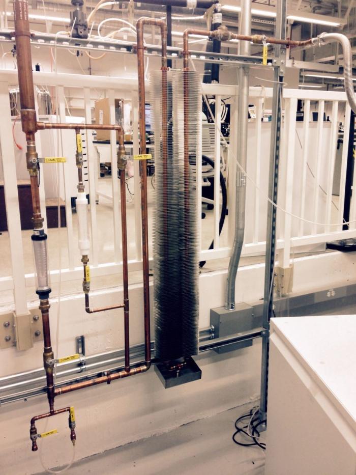
The finned tubing is intended primarily to heat the helium exhaust gas from a fill closer to room temperature, so as to avoid damaging down-stream components. The flow meters are intended to provide a way to monitor the helium exhaust to determine the end of a fill (the helium exhaust will increase when the magnet is full, compared to during steady-state filling). Using a helium level meter during a fill can be unreliable. On our system, the smaller meter (white) works reasonably well for fills, although the white-colored float is difficult to see in the white tube. Coloring the float black with a permanent marker can help. The larger meter has too much back pressure unless the float is replaced with something much more lightweight, such as a 1” diameter styrofoam ball. Neither flow meter is ideal for the intended purpose because they overly restrict the flow. We are considering the idea of using an enclosed anemometer, similar to those used for HVAC work, as a better flow meter option.
Prior to installation of the helium recovery system, the plumbing of the manifolds and headers should be put on a vacuum pump for at least a week to remove contamination (solder flux, water, etc.) – this will greatly improve the initial operation of the recovery system. It is also a good way to find leaks in the system, such as in the flow meters. We were able to pump our plumbing down to 10^-4 torr after finding and correcting leaks.
Finally, it is a very good idea to have a way to continually monitor for leaks in the system. There are portable helium leak detectors based on mass spectrometers which are ideal for the task, but these can be somewhat expensive. For our purposes we have found that a “Thermal Conductivity Gas Leak Checker”, often used to find leaks in a GC-MS, works well enough.